Saturday, February 29, 2020
The home stretch
I got it all put together and it looks excellent!
It took another 4 hours of coding to iron out all the bugs. I also wrote an anti-cathode poisoning routine.
Basically every 5 minutes (at xx:x4:59) it cycles through 0-9 on all nixies. It displays each number for 100 ms. For a total of 1 second of slot machine like action :)
Then at 3AM it cycles each digit 0-9 for 30 seconds each. So the clock won't be readable between 3 and 3:03AM, but hopefully I'm sleeping when it is doing that ;)
I removed all other HP boards from the counter, so it is just the power supply board and the nixie display board.
For now, I'm going to leave it in 24 hour time.
I may later add separator neon bulbs or LEDs between the hours, minutes, and seconds. But this display is so compact, there isn't much room for them.
Now I'm going to run it for a while and see how it holds up.


Friday, February 28, 2020
All 6 digits wired up
I finally got all 6 digits wired up. I connected them with wire-wrap. I just got some new colors in the mail today, so I made each 74HC595 a different color.
I spent a couple hours troubleshooting the code and figuring out how to add, subtract, multiply, and logical shift << >> a byte in binary, so that the digits read from the RTC could be output to the shift registers. I'm sure there is an easier way, but I ended up converting the time from an integer to a character, then splitting the number into each digit, then using a lookup table to select the correct binary code for each number. Then I put it in a variable, << 4, then added the second digit. I ended up with something like this 0b11110101. Then I shifted that out to the 74HC595 with a function.


I spent a couple hours troubleshooting the code and figuring out how to add, subtract, multiply, and logical shift << >> a byte in binary, so that the digits read from the RTC could be output to the shift registers. I'm sure there is an easier way, but I ended up converting the time from an integer to a character, then splitting the number into each digit, then using a lookup table to select the correct binary code for each number. Then I put it in a variable, << 4, then added the second digit. I ended up with something like this 0b11110101. Then I shifted that out to the 74HC595 with a function.


Thursday, February 27, 2020
2 digits wired
Made some more progress on the nixie clock project. I got two digits
wired up. It took an hour or two to debug a software issue where it
wasn't displaying the correct digit, but I finally figured that out.
Just need to wire up the other 16 pins and then do a little bit more
coding


Wednesday, February 26, 2020
IC removal
I decided the easiest way to control the 1920-0092 driver chips would be to desolder the HP 1820-0116 4 bit latch chips.
Now I can solder wires to the driver chips without interference from any of the original digital logic.
I got all 6 chips removed and did some signal tracing. I found the GND, +5, and HV pins.
Next I'll hook up the 24 control wires to my 74HC595 chips and then power and ground.
Then I'll be ready for some testing...


HP 5321A teardown
It took a little while to figure out how to extract the main nixie board from the counter, but I finally figured it out. I had to use two screwdrivers to pry up the board in two spots in order to slide it out the front.


Testing board
I temporarily wired up this 10 nixie board and did some testing. The nixie digits do light up when the correct pin is grounded.
I have to build a dual voltage (12v and 5v) power supply circuit to properly test this entire board, so I'll do that later...


I have to build a dual voltage (12v and 5v) power supply circuit to properly test this entire board, so I'll do that later...


Tuesday, February 25, 2020
Tracing traces
Now that I have the pinouts for the 1920-0092 chips, I was able to determine what traces did what on this 10 nixie board. +5, GND, and HV were easy to identify.
Soon I'll hook up my test power supply and test the nixies on this board.


Soon I'll hook up my test power supply and test the nixies on this board.


Standalone switching Nixie Power supply
For testing purposes I built this small nixie power supply. With a 390 ohm set resistor it puts out around 180 volts. I'll use it to test the HP nixie display boards.
https://threeneurons.wordpress.com/nixie-power-supply/hv-supply-kit/


https://threeneurons.wordpress.com/nixie-power-supply/hv-supply-kit/


More wire wrap
The board is about 90 percent complete. I got all three 74HC595 ICs wired up. I also got the RTC wired up and working. The only thing I may do is add circuitry for driving two separate neon lamps at a later time. (4 transistors and a few resistors.
I hooked it up to the computer and initialized the RTC.
The Arduino and RTC are working great.


I hooked it up to the computer and initialized the RTC.
The Arduino and RTC are working great.


Monday, February 24, 2020
building a board
Today I started on building a board. It will be fairly simple. With just an Arduino Nano, RTC, and 3 socketed 74HC595 chips. I may add a couple transistors for turning on decimal points or neon bulb separators later.
I've decided to do a little Wire Wrap for speed rather than point to point soldering everything.


I've decided to do a little Wire Wrap for speed rather than point to point soldering everything.


Doing some code and hooking up the RTC
I wrote a byte Array that is indexed by an integer that is the same as the digit that I want to activate. This is what I'll use as a translation between digits and ABCD values from the 74HC595.
I also hooked up an RTC. This Real Time Clock is based on the DS3231 chip.


I also hooked up an RTC. This Real Time Clock is based on the DS3231 chip.


Testing the drivers and shift registers
I wired up 20 LEDs to two HP 1820-0092 drivers. Then connected those to to a single 74HC595.
I was able to drive an individual LED (simulating a digit of a nixie tube) on each driver using the Arduino.

I was able to drive an individual LED (simulating a digit of a nixie tube) on each driver using the Arduino.

Sunday, February 23, 2020
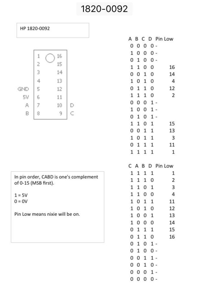
HP nixie driver chips 1820-0092
The most common nixie driver is the 74141 or its Russian equivalent K155ID1.
A lot less common is the HP 1820-0092. There is a later version of that chip also called the 1820-0729. These nixie drivers do the same thing, a BCD to 10 output driver. The pinout is different than the Russian version.
It took a bit of research but I finally found the pinout and a truth table for this IC. The information comes from an HP 5321B frequency counter manual.
https://literature.cdn.keysight.com/litweb/pdf/05221-90014.pdf?id=1869796
This is the information that I needed. I can now send the appropriate 1s and 0s via the 74HC595 chip to activate the correct digits.


https://www.nixies.us/resources/hp-1820-0092-nixie-driver/
A lot less common is the HP 1820-0092. There is a later version of that chip also called the 1820-0729. These nixie drivers do the same thing, a BCD to 10 output driver. The pinout is different than the Russian version.
It took a bit of research but I finally found the pinout and a truth table for this IC. The information comes from an HP 5321B frequency counter manual.
https://literature.cdn.keysight.com/litweb/pdf/05221-90014.pdf?id=1869796
This is the information that I needed. I can now send the appropriate 1s and 0s via the 74HC595 chip to activate the correct digits.


Subscribe to:
Comments (Atom)